


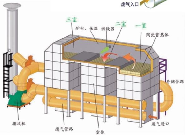
RTO regenerative catalytic oxidation equipment
Key words:
Biochemical treatment equipment
Flotation equipment
Classification:
RTO regenerative catalytic oxidation equipment
RTO heat storage bed working state periodic table
| Time | T | 2T | 3T | ||||||
| A bed | Intake | Purging | out of gas | Intake | Purging | out of gas | Intake | Purging | out of gas |
| Bed B | out of gas | Intake | Purging | out of gas | Intake | Purging | out of gas | Intake | Purging |
| Bed C | Purging | out of gas | Intake | Purging | out of gas | Intake | Purging | out of gas | Intake |
Common size table/Common Specification size table
| Air volume (Nm" h) (Nm" h) | 两室RTO占地(m²) Two rooms RTO covers(m²) | 三室RTO占地(m²) Three-room RTO covers an area(m²) |
| 5000 | 4 × 2 | 7 × 2 |
| 10000 | 6 × 2.7 | 8.7 × 2.7 |
| 20000 | 7.5 × 3 | 11x3 |
| 30000 | 9 × 3.2 | 13.5 × 3.2 |
| 40000 | 10 × 4.2 | 14 × 4.5 |
| 50000 | 11 × 4.5 | 15 × 4.5 |
| 60000 | 11 × 5.6 | 16 × 5.6 |
性 能 特 点 /The Performance characteristics of
RTO uses high-efficiency heat storage ceramics for heat storage and heat release to realize heat conversion. Heat storage ceramics are customized high-efficiency ceramics with low wind resistance, high thermal efficiency and excellent thermal shock resistance. The heat storage ceramic adopts a special customized U-shaped groove structure, which can reduce the resistance of the heat storage ceramic area by more than 30%, reduce the power consumption of the system fan, and redistribute the exhaust gas in the flow process to ensure uniform gas flow in each area of the heat storage bed.
The inside of the RTO box adopts a high-alumina aluminum silicate fiber insulation module with a maximum insulation thickness of 250mm, and the insulation effect is better than that of ordinary aluminum or high-purity fiber cotton. Thermal insulation shall be carried out in accordance with the requirements of GB4272 General Principles for Thermal Insulation Design of Equipment and Pipes, and warning signs shall be set at high temperature parts. Use a thermal imager to actually measure the external surface temperature: the external surface temperature shall not be higher than the ambient temperature by 40 ℃ (except for the burner part).
The burner system is a well-known foreign brand, international FM certification, and customized products for the company. The burner is a continuous proportional adjustment type (automatically adjust the gas volume according to the needs of the system), with a metal safety valve, with a large adjustment ratio, the fuel is fully burned, and no secondary pollution of NOx and CO is formed. The combustion chamber is provided with a viewing hole (mirror), Safe and reliable, long service life. The fuel and gas pipeline of the burner system adopts European standard design, double shut-off valve design, flame UV detector and Honeywell controller. The proportional regulating valve adjusts its opening according to the temperature change required by the furnace, saves fuel, and synchronously adjusts the flow of fuel and combustion-supporting air to maintain a certain proportion and achieve stable and complete combustion. The fuel gas pipeline contains a pressure regulator valve to stabilize the gas supply pressure and also contains high and low pressure protection. If the front pressure is too low or too high due to problems with the pipeline or valve in front of the burner, the low pressure or high pressure protection is opened and the solenoid valve automatically cuts off the fuel. The UV flame detector senses the flame of the burner at all times. During normal combustion, the flame signal shows that when there is no flame, the solenoid valve in the fuel supply pipeline is closed; when the combustion flame is extinguished, the solenoid valve in the fuel supply pipeline automatically closes and cuts off the fuel. Safety protection. The in-place signal of the main shut-off valve of the burner is connected with the PLC control, and the alarm will be given immediately if the valve is not closed in place.
● The metal-to-metal airtight and almost zero-leakage double-disc design switching valve design can achieve 99% VOC removal efficiency without the need for additional purge storage tanks or other equipment.
● Removal efficiency meets environmental regulations.
● The flexibility of the system can meet a wide range of process conditions, and can easily control multiple process waste gas sources.
● The customized thermal storage ceramic layer can provide 95% heat recovery, and its pressure drop is small, reducing the power demand of the fan.
● Excellent cost performance.
● Short time required for system installation.
● It takes up less space.
Scope of application/Scope of application/
It is suitable for the treatment of mixed combustible organic waste gas and odor with medium and large concentration (thousands of ppm) and medium air volume. The waste gas treatment of electronic products manufacturing and integrated circuits. The waste gas treatment of printing process and injection molding process. The treatment of organic waste gas generated by petrochemical, medical and other industries
Related Products

")


Get a Product Quote
Jingshan Haojie Intelligent Environmental Protection Machinery Technology Development Co., Ltd.
Contact: Mr. Dong+86-13928844138 +86-13774077867
E-mail:1017645596@qq.com
Address: Industrial Plant in the Western Half of Building E2, Intelligent Industrial Park, Jingshan Economic Development Zone, Jingmen City, Hubei Province
Official website:http://en.haojie668.com/
Focus on us

Sweep Code Add
Copyright©2024 Jingshan Haojie Intelligent Environmental Protection Machinery Technology Development Co., Ltd.